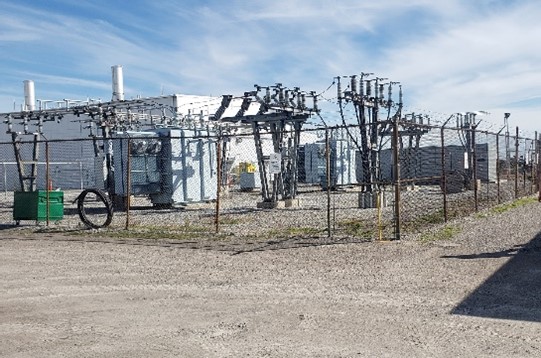
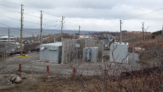
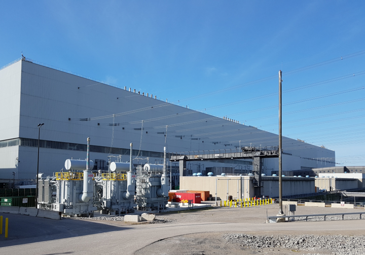
The Utility’s grid was converted from 22kV to 44kV as part of their power grid modernization program. The hydroelectric generation station is connected to the Utility’s grid and the output voltage had to be changed from 22kV to 44kV to match the Utility’s new grid parameters. The scope included the construction of an outdoor substation compound to house a new main output transformer (MOT), Revenue CTs and PTs on pedestals,
interrupter, switcher, lightning arresters and the O/H line exit structure for connection to Utility’s overhead line.
The project scope also included the upgrade of the SCADA system and the upgrade of the MOT and line protection.
Electrical Engineering services included the protection and controls upgrade, and the design for the power distribution and generator paralleling switchgear upgrade, communication system, lightning and surge protection, panels, wiring, medium voltage overhead and underground raceways, protective devices, switcher, interrupter, and insulators.
The Utility’s grid was converted from 22kV to 44kV as part of the grid modernization program. The Hydroelectric Generation Station, , is connected to the Utility’s grid and the output voltage had to be changed from 22kV to 44kV to match the new grid parameters.
The scope of project included replacing the main output transformer (MOT) and the installation of a new high voltage interrupter (HVI), protection & revenue CTs & PTs, station protection relays, revenue metering, cabling and related equipment. The new power delivery system was re-connected to the Utility’s upgraded 44 kV distributionline. There was insufficient space within the Generating Station to install the new 2.3-44kV MOT, and the transformer along with all 44kV components had to be installed outside in a new Switchyard located adjacent to the Generating Station. The design for this Switchyard was also provided by Algal. The scope additionally included a new transfer trip system and rural power service.
This hydroelectric generation station uses cellular modem technology to establish communications for the SCADA network, as there are no other reliable communication options available in the area. However, the cellular modem technology did not meet the operational requirements for this station and the solution was the implementation of a fixed telecommunication infrastructure between the stations.
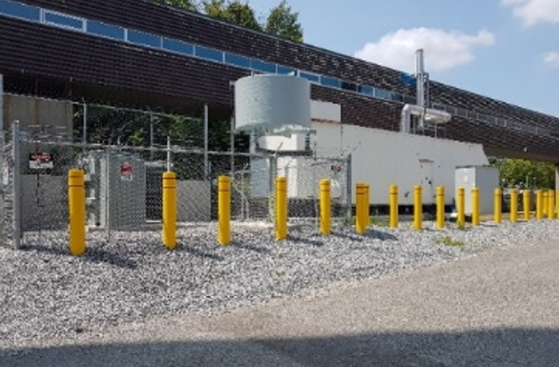
The main objective of the client was to establish high-speed communications with the other generating stations in the area to meet operational needs. The project intent was to install a microwave tower as well as a communication shelter which enabled the extension of the high-speed communication circuits to the Stations for providing SCADA and IP Networking solutions.
This hydroelectric generating station used cellular modem technology to establish communications for the SCADA network as there are no other reliable communication options available. The existing cellular modem technology was not meeting the operational requirements for these Stations. The solution was the implementation of a fixed telecommunication infrastructure between the two hydroelectric generating stations.
The main objective for the clientwas to establish high-speed communications between the Generating Stations to meet operational needs. The client was seeking to install a microwave tower as well as a communication shelter that would enable them to extend the high-speed communication circuits to the Stations so as to provide SCADA and IP Networking solutions.
Algal Engineering provided the design, engineering field and commissioning supports for this project.
Algal provided electrical engineering services for the design and implementation support for the station AC and DC system refurbishment at this OPG Generating Station. The project included the upgrades of the station service power distribution, MCCs replacement, a new SCADA system, the upgrade of the transformer and generator protection systems, as well as new lighting and lighting control.
The scope also included the evaluation and upgrade of the grounding system, cable management system and replacement of the aged AC and DC cables.
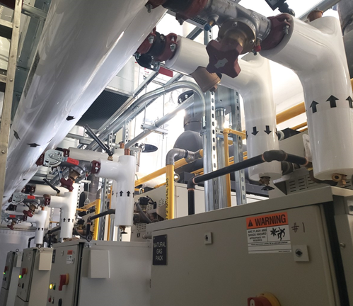
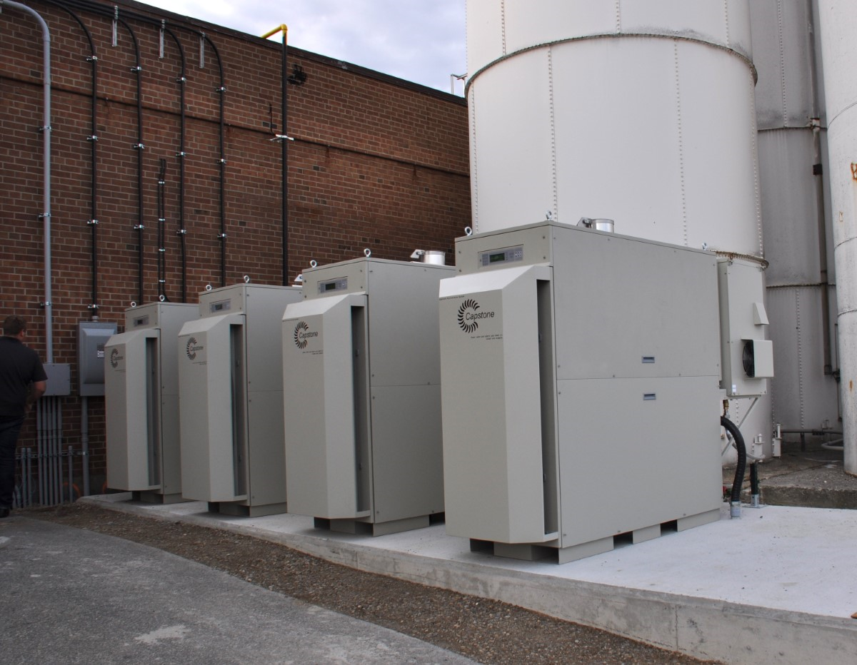
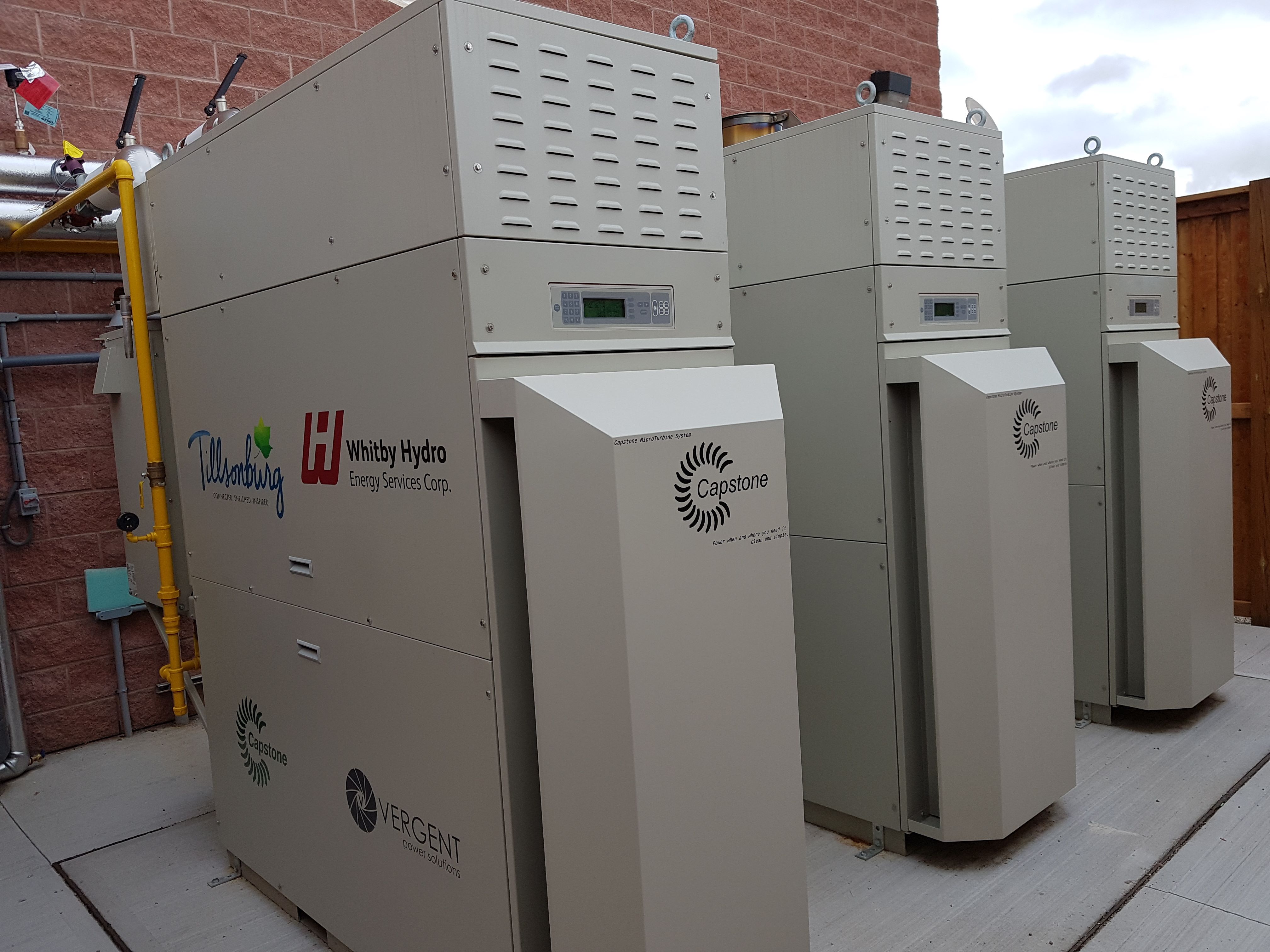
Algal provided the design and project administration services for the installation of six (6) Combined Heat and Power units (CHPs). The co-generation system was designed to offset a large part of the Utility power used by the building, which offers substantial cost saving. The calculated payback period was 3.5 years.
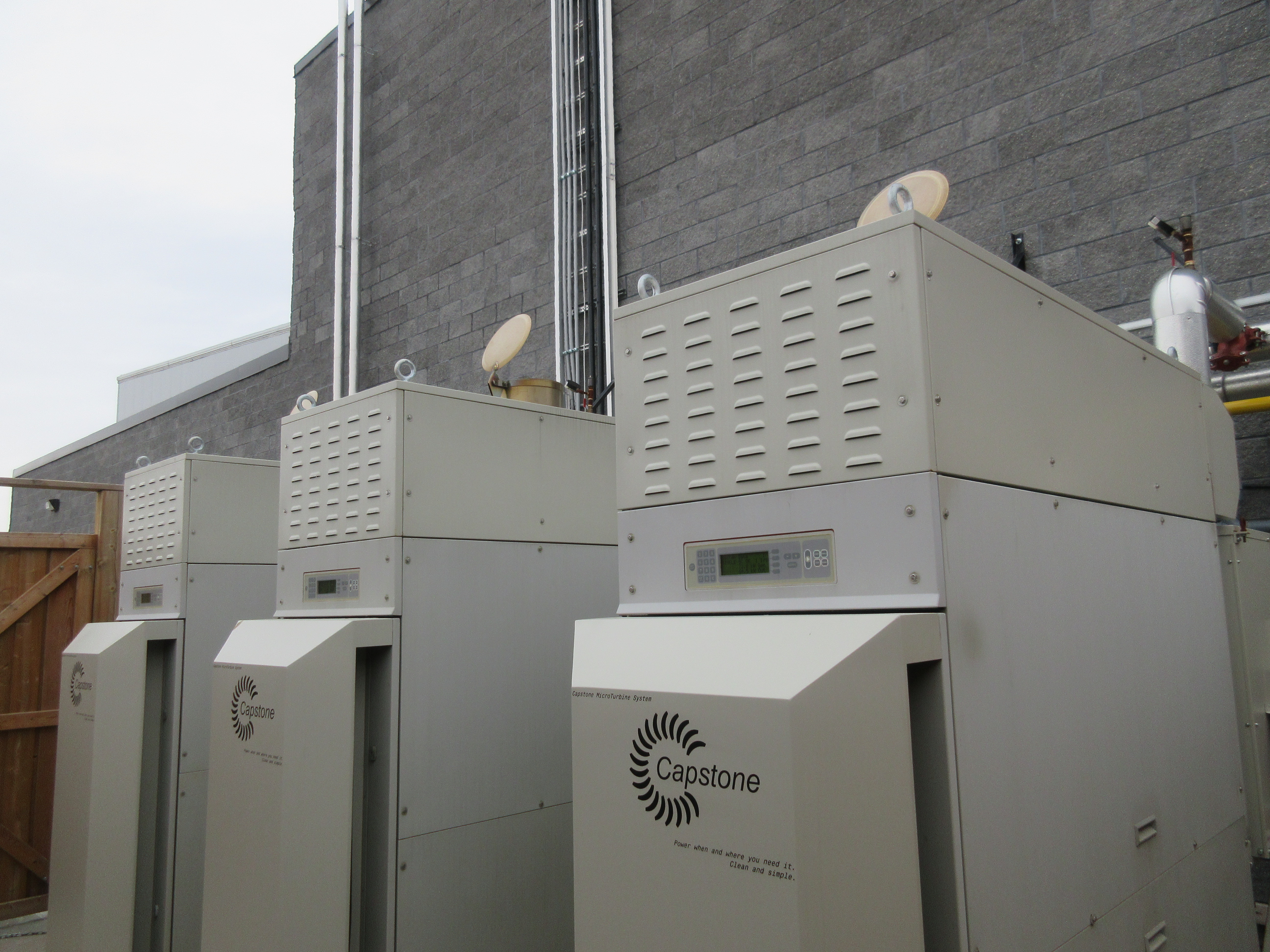
These CHP microturbine units are located outdoors at the rear of the building. The electricity produced is injected into the main switchgear with reverse power protection, as required by the Toronto Hydro Distributed Generation Policy
The project involved a multi-disciplinary engineering team including electrical, mechanical, structural, civil, and geotechnical engineering services as well as environmental consulting services.
Algal Engineering played the role of Prime Consultant for the project.
The project involved the Installation of three Dual-Mode, 3 x 65 kW Capstone Microturbine Cogeneration Plant (195 kW in total).
This cogeneration plant also acts as an emergency backup power supply for the life safety systems. The unit controls are performed by a Capstone DualMode System Controller which acts similar to an automatic transfer switch.
Algal’s Design also included the segregation of life safety loads from the rest of the building loads in order to obtain the required load shedding for emergency power distribution in the case of Utility power failure. The heat generated by the microturbines is used for building heating and it is injected into the heating loops via a heat exchanger.
The efficiency of the system is around 85% and the capital cost simple payback was calculated at 3.1 years.
The project involved a multi-disciplinary engineering team including electrical, mechanical, structural, civil, geotechnical engineering services as well as environmental consulting services.
Algal Engineering played the role of Prime Consultant for the project.
This project entailed the installation of a new Dual Mode 3 x 65 kW Capstone Microturbine Cogeneration Plant at a sports centre and arena in Southeast Ontario. Algal Engineering provided electrical engineering services and also coordinated a multi-disciplinary engineering team as Prime Consultant.
This cogeneration plant also acts as an emergency backup power supply for the arena’s life safety systems. The unit controls are performed by a Capstone Dual Mode System Controller which acts similar to an automatic transfer switch. Algal’s Design also included the segregation of life safety loads from the rest of the building loads in order to obtain the required load shedding for emergency power distribution in the case of Utility power failure.
The heat generated by the microturbines is used for building heating and it is injected into the heating loops via a heat exchanger. The efficiency of the system is around 83% and the capital cost simple payback was calculated at 3.4 years.
Algal provided electrical engineering services for the installation of a new 65KW Capstone Microturbine Cogeneration Plant.
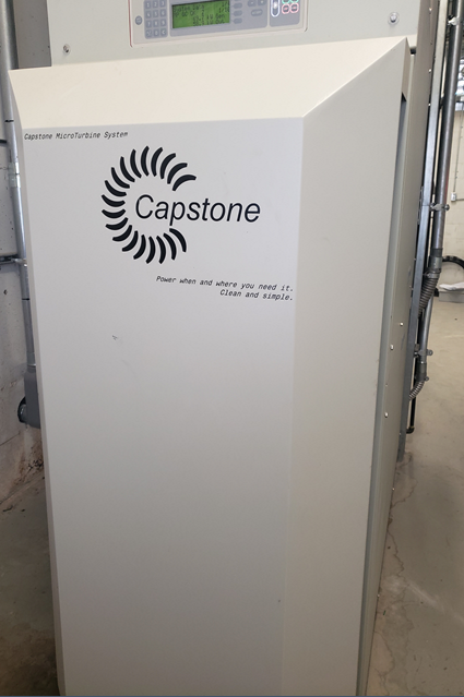
The co-generation system was designed to offset a part of the Utility power used by the building, offering substantial cost saving. These CHP microturbine units are located indoors in the mechanical room. The electricity produced is injected into a motor control center with reverse power protection as required by the Toronto Hydro Distributed Generation policy.
The heat generated by the microturbines is used for building heating and it is injected into the heating loops via a heat exchanger. The efficiency of the system is around 85% and the capital cost simple payback was calculated at 3.3 years.
The project involved multi-disciplinary engineering team including electrical, mechanical, and structural engineering services. Algal Engineering played the role of Prime Consultant for the project.
In this project, Algal provided electrical engineering services for the installation of four 4x65kW (260kW) Capstone Microturbine Cogeneration Plant.
This plant was intended to increase the residential building’s cost saving by offsetting the use of Utility Power through the implementation of the microturbine plant. The calculated payback period was 3.5 years.
Algal designed the four microturbine CHPs to be located inside the mechanical room based on space availability. The electricity produced is injected into a motor control center with reverse power protection as required by the Toronto Hydro Distributed Generation policy.
In addition to offsetting power use, the heat produced by the microturbines was used to heat the building through injection into heating loops via a heat exchanger.
Algal Engineering acted as Prime Consultant for a multi-disciplinary engineering team including electrical, mechanical, structural engineering services.
This facility was a major shipping/postage facility for a top mail/parcel distributor in Canada.
It is a strategic and essential facility for the operation of the distributor and was central to the operations.
The MPP had an emergency power generator for life and safety and some process equipment. However, the existing system did not have the capability for a quick connection for an alternate recovery generator in the case of a critical or catastrophic failure of the Utility Power Supply. Algal Engineering provided design for a 600V generators connections to cover the full required capacity for complete recovery. The system was designed to offer an automated transfer switch between two 44kV power utility feeders as well as a second level of back-up by paralleling three 2MW generators and a step-up transformer capable to take over the entire facility load in case both utility feeders are not available.
The power back-up system is connected via underground feeders to the main 44kV switchgear and provides a high reliability configuration capable of offering two layers of back-up. Algal Engineering provided Electrical Engineering and provided multi-disciplinary team coordination as the Prime Consultant.
The building complex is an important Ministerial Lab Facility. The facility houses sophisticated and sensitive laboratory equipment which is used for various sampling tests.
The reliability and availability of power supply is essential for the equipment operation and protection as well as for the continuity of ongoing lab tests. The sensitive equipment was backed-up by two diesel generators and a network of UPS systems. However, there were power loads that were connected to the generators, and they were affected by Utility power failure, negatively impacting the Lab and office activities. To increase the power supply reliability for the facility, a third generator system was installed to back-up the balance of the loads. Algal Engineering was engaged as Prime Consultant to coordinate a multi-disciplinary engineering team for the design, installation and commissioning support.
The system is based on an automatic medium voltage transfer scheme that switches from the 27.6kV Utility Feeder to a back-up generator system offering continuity to the power supply for the entire facility. The design entailed the modification of the main 27.6kV switchgear, new transfer scheme based on medium voltage breakers and interlocking PLC control system, medium voltage generator, neutral grounding reactor, step-up transformer, grounding system, cables, generator fuel system and other auxiliary components.
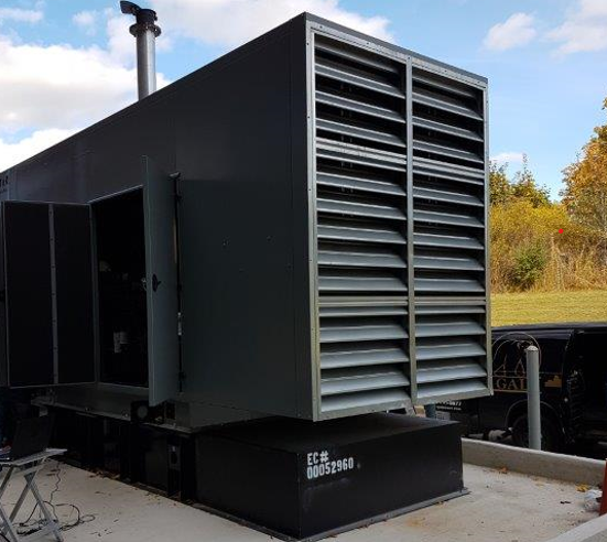
The scope for this project included the design/engineering and contract administration for the removal of the existing emergency power generator system and the installation of a new emergency generator to provide 100% back-up power for the site. The required size of the new generator, determined during the Feasibility Study, was 1500kW.
The new generator was installed outdoor in a fully winterized and sound attenuation enclosure. New feeders, service entry and an automatic transfer switch (ATS) were required to connect the new generator to the existing power distribution systems in the building. The generator is a dual-fuel type and is connected to the Gas Utility grid and also has an integrated sub-base diesel storage tank capable to run the generator for 72 hours on diesel and for an unlimited time on the gas supply.
The design required the collaboration of a complex engineering team including electrical, mechanical, civil, structural, geotechnical and environmental engineering.
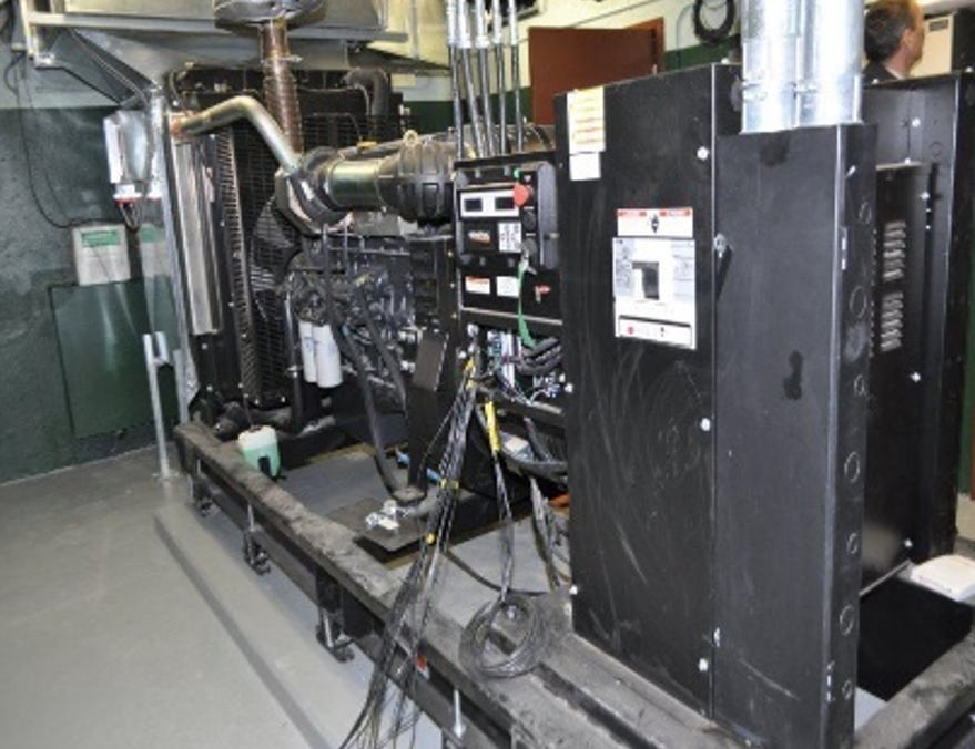
This project required the installation of a new generator set in the basement level of a Government Building sized to cover the existing loads and to provide sufficient contingency for the life safety loads and other critical loads.
The project entailed the design and installation of:
- A new generator room, complete with the required louvers, heating, lighting cooling and ventilation.
- A new emergency generator system, complete with noise attenuation muffler system, fuel tanks, fuel system, exhaust stack and auxiliary components.
- A new emergency power distribution system throughout the government building to connect to the new life safety emergency generator. The intent was to separate the life safety loads and move them to the new generator and leave only the critical tenant program loads that require power back-up on the existing generator.
Algal reviewed the existing critical tenant program loads and confirmed that the existing generator can handle them safely. Algal also updated the single line diagram for the entire power distribution system as part of the project deliverables.
A new protection coordination study for the new power distribution system was also delivered as part of the engineering design package. Algal Engineering provided design, project coordination, installation and commissioning support and prime consulting services for the project.
The Buildings were created for response systems in emergency situations and the cooling control system of the plant. The reliability of the power supply is very important for the correct and safe operation of the facility. To increase the reliability and availability of the power system of the buildings, a dedicated back-up diesel generator system was designed and installed. The scope of this proposal included two main components as follow:
1) Assessment and design for 4.16kV overhead line reconfiguration or replacement in order to increase the reliability and availability of medium power supply to the Eastern side of the PNG site. Algal prepared an Assessment Report presenting existing systems, options, option analysis and recommendations for the line upgrades as well as the preparation of the conceptual design for the upgrade of the overhead power line system.
2) Assessment and design of emergency power supply for the buildings. The design included the following deliverables:
a) Generator sizing and stability calculations.
b) Electrical technical and construction specification.
c) Bill of materials.
d) Site Plan, equipment layout and elevations.
e) Diagrams: Single-line diagram, CWDs, Controls.
f) Structural and civil engineering drawings and specifications.
g) OPG affected drawings mark-ups.
h) Commissioning Plan and ITP.
Algal Engineering was the electrical design engineer and prime consultant for the project.

The plant is composed of the Nuclear Generation Station as well as several support office and technical buildings located in the campus both inside and outside of Protected Area (PA). In preparation for the plant refurbishment, the electrical infrastructure of the entire site was to be upgraded to accommodate the existing and new building systems and structures. The new electrical systems had to be integrated with existing Plant and Utility connections.
The scope of this project was the design of a substation’s system structure and its integration into existing Plant and Utility systems.
Algal Engineering provided a design package for the integration of the new electrical system into the site and plant systems, including the following:
a) Integrated the new substation into the 44kV Utility distribution feeder including, O/H line tie-in, feeder protection, lightning protection and primary revenue metering.
b) Coordinated the substation’s protection system with the utility’s transformer and line protections.
c) Integrated the new substation systems with the existing plant site systems including:
- Protection coordination between the feeder breakers in the new switchgears and the downstream power distribution protective devices, including the satellite switchgears, transformer and service protection for selected buildings.
- New power distribution interconnected with existing power infrastructure on site.
- Fire alarm system integrated into the plant’s fire protection system, initiation, alarm and remote annunciation.
- Public address system integrated within site’s general PA system via telephone infrastructure.
- Communication in the substation interconnected via copper infrastructure to the site telephone system and to Bell telephone lines.
- Network fiber optic integration of the IT rack into F/O infrastructure of the site.
- Remote control of breaker tripping via a control panel.
- Remote annunciation of all alarms to the monitoring station in the Main Security Building.
- Interconnection and integration of the station system’s grounding grid with the existing grounding grid of another substation’s, 8.32kV system and the Nuclear Generation plant grounding grid. The design included a comprehensive grounding study to evaluate the performance of the overall site grounding grid after the interconnection of new DS5 grid.
d) Integrated the new substation and switchgear systems with the existing site systems including:
- Protection coordination between the new substation, 44kV incoming feeder fused protection and the switchgear feeder breaker protections and downstream protections buildings.
- New power distribution interconnected with existing power infrastructure on site at 44kV level and downstream integration into existing building systems.
- Switchgear interconnection via copper infrastructure to the site telephone system for remote annunciation of status and alarms.
- Remote control of breaker tripping via a control panel.
- Remote annunciation of all alarms to the monitoring station and mobile cell phone annunciation.
The Plant is composed of the Nuclear Generation Station and several support offices and technical buildings located at the Campus. The buildings outside the protected area are fed from a 44kV/4.16kV substation. The substation was built as a power supply for the construction of the Nuclear Plant and has continued to operate until present.
The main components and tasks for the substation design are the following:
- Performed a connection impact review with the Power Utility
- Reviewed the demarcation point with the Power Utility and determined the isolation points.
- Presented the Design Briefing to the Electrical Safety Authority (conducted a meeting on-site with ESA Inspector).
- Presented the Design Briefing to the Power Utility (conducted a meeting on site with the Utility). Obtained acceptance on the proposed modification of 44kV line.
- Prepared a load calculation per feeder as well as for the entire Substation.
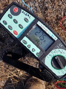
- Performed soil resistivity measurements and conducted a fall of potential to assess the performance of existing grounding grid.
- Coordinated the work of all subconsultants (Civil, Structural, Environmental, Geotechnical, U/G systems locate, Topographic.) Prepared the substation site plan.
- Prepared the design for incoming dual feeders 44kV including drawings and specifications (pole schedule, wire schedule, anchoring schedule, sag and tension calculations, bill of materials)
- Prepared the specification of long lead equipment (main 44kV fused switches, transformers, 5kV switchgears)
- Prepared technical and construction specifications for the complete project.
- Contacted equipment manufacturers and made the selection of equipment. Discussed delivery schedule and constructability aspects.
- Discussed the requirements related to the metering system with the Utility. Made equipment selection and obtained Utility and Plant’s acceptance.
- Prepared new drawings, specifications, bill of materials, inspection and test procedures, commissioning specification.
- Prepared the grounding study and grounding system design.
The plant is composed of the Nuclear Generation Station and several support buildings. Most of the buildings located outside the protected area are fed from a 44kV/4.16kV substation. The substation was built as a power supply for the construction of the Nuclear Plant and has continued to operate until present.
The refurbishment and upgrade of substation DS1 was included in the work plan for the upgrade of power distribution system to support the refurbishment of the Nuclear Generation Station.
The scope of the substation refurbishment included mainly the following:
- Provided technical specifications for the Over Current Reclosers (OCR), power distribution panel boards, manual transfer switch, cables and cable management, power transformers control cabinets.
- Designed underground cable arrangement. Designed the inground recessed cable raceways.
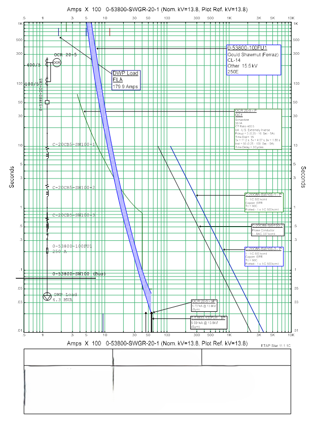
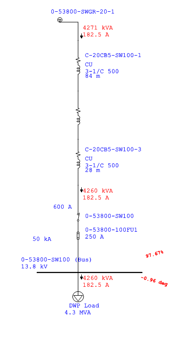
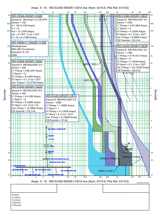
- Performed protection coordination, short circuit and load flow study for the new and upgraded system using ETAP software. Algal Engineering modelled the system using ETAP software and provided a report including analysis, conclusions, protection settings and sizing, type, make and model of the protection devices.
- Algal Engineering prepared new drawings and marked the existing plant electrical drawings which were affected. A bill of materials, associated to the design drawings, was also a part of the design package.
- Provided grounding and bonding design for the medium and low voltage sections.
- Prepared the Substation Refurbishment Plan and Installation Specification.
- Prepared the Inspection and Testing Procedure for all equipment within the substation compound.
- Prepared documentation for the Electrical Safety Authority Plan Review Department.
- Interacted and coordinated with other engineering disciplines during the design and design coordination sessions.
- Provided engineering filed support, oversight and supervision during the installation and commissioning phases.
The plant is composed of the Nuclear Generation Station and several support buildings. The role of the old Auxiliary Heating Plant Facility was to deliver heat to the Nuclear Generation Station when the Station Services are not available due to a power outage. The Heating Plant had four electric boilers which were electrically fed from a medium voltage substation. The substation was not connected to any other load.
As part of a refurbishment project a new heating plant was planned to be built in place of the old Auxiliary Heating Plant. The power feeder for the new heating plant was to be connected to the substation. This refurbishment project was scheduled in order to extend the life of the substation and improve its reliability.
The refurbishment and upgrade of substation DS2 was included in the OPG work plan for the upgrade of the power distribution system to support the refurbishment of the nuclear generation station.
The scope of the substation refurbishment mainly included the following aspects:
- Provided technical specifications for the medium voltage breaker type switchgear, power distribution panel boards, cables and cable management, transformers and cables, power transformers control cabinets, forced air cooling system, remote control for breaker operation, station service system.
- Designed the underground cable arrangement and underground duct banks.
- Performed protection coordination, short circuit and load flow studies for the new and upgraded system using ETAP software. Algal Engineering modelled the system using ETAP software and provided a report including analysis, conclusions, protection settings and sizing, type, make and model of the protection devices.
- Algal Engineering prepared new drawings marked affected plant existing electrical drawings. A bill of materials, associated to the design drawings, was also part of the design package.
- Provided grounding and bonding design for the medium and low voltage sections.
- Prepared the Substation Refurbishment Plan and Installation Specification.
- Prepared the Inspection and Testing Procedure for all equipment within the substation compound.
- Prepared documentation for the Electrical Safety Authority Plan Review Department.
- Interacted and coordinated with other engineering disciplines during the design and design coordination sessions.
Provided engineering field support, oversight and supervision during the installation and commissioning phases.
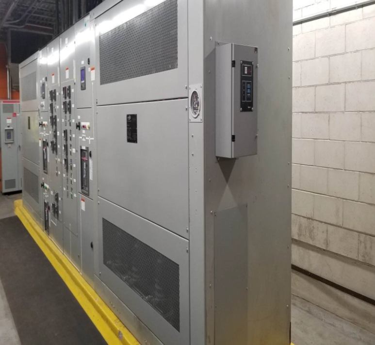
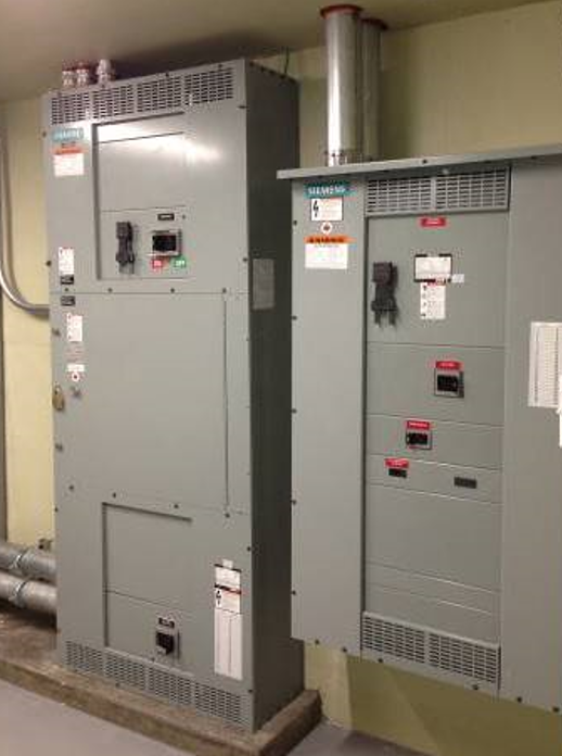
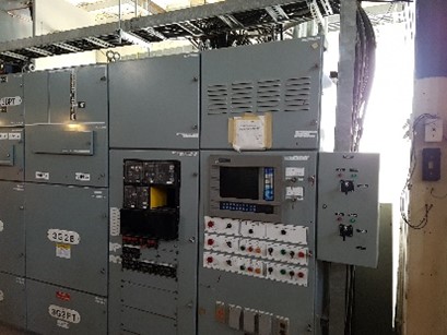
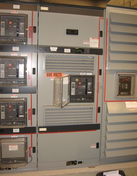
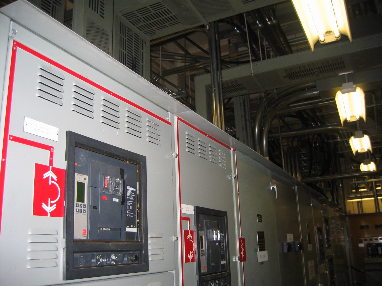
The scope of this project was to provide Engineering Services for the design and field support required for the retrofit of three existing 13.8kV/0.6kV substations located inside a mailing/shipping facility.
All three substations are fed from the main 13.8kV switchgear located in an electrical room and are two-side switchgears with input voltage of 13.8kV and secondary 600V, with internal dry-type stepdown transformers. The switchgears are configured for 100% redundancy with a tie-breaker rated at full load.
The objective of the project was to refurbish/upgrade the three substations as follows:
- The switchgear’s existing metal enclosure was refinished with new paint which was applied on site.
- Installed new metal frames for the breaker sections which were custom made to match the frame of existing switchgear. The new panel frames were factory finished to match the substation enclosure finish.
- Replaced existing transformers with new dry-type transformers in the same enclosure.
- Replaced all breakers, mains and distribution branch breakers. The bus system was assessed and upgraded as required. In order to fall within the power shut down duration restrictions , Algal considered a new insert complete with breakers for each distribution section.
- Implemented a manual control scheme to allow for remote control (tripping and reset) of main breakers and tie breaker.
- Implemented an automatic transfer system to shift the load to the other transformer in case of failure of one transformer or its incoming feeder.
- Replaced the existing Metering System.
- Integrated the Power Distribution System into the existing BAS for monitoring and alarm purposes.
- Assessed the Grounding System by performing visual inspection and tests in line with our Work Methodology.
- Algal Engineering hired a specialized Contractor to perform power monitoring for one month for all three substations. There were six points of monitoring considered and the results were used for verification of new equipment sizing.
- Due to space limitations, the modification of structural elements was required for the accessibility of moving new equipment into the substation rooms. Additionally, we verified the structural withstanding capacity of the existing roof, in case the equipment had to be craned to the existing roof before it was moved into the Mechanical Penthouse.
- Provided and installed updated stamped laminated Single Lines Drawings in each electrical room inside the building.
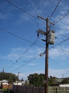
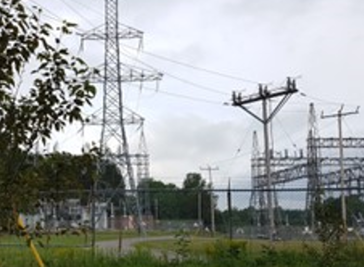
This project was done for a power utility in Northern Ontario that served tens of thousands of people. The vast majority of the medium voltage distribution system for this utility was based on overhead lines on wood poles. Some newer developments are fed via an underground grid.
The Utility launched a large power distribution upgrade and voltage conversion from 4kV to 25 kV.
Algal Engineering was the Design Agent in charge of the design and installation engineering support for medium and low voltage power distribution in multiple areas totaling around 1,600 poles and more than 100 transformers.
The total number of poles replaced in various regions/neighborhoods serviced by the utility totalled more than 1,550 poles
Algal Engineering’s scope of services included the following:
• Detailed audit of the existing overhead power distribution infrastructure and the preparation of the rebuild design package including new lines, new connection points, and load balancing within project area.
• Prepared three-line diagrams for the 4kV and 25kV distribution systems including demolition and new installation.
• Produced layout drawings identifying all poles that had to be replaced as well as all necessary pole framing, protections, anchoring, wiring and equipment sizes and installation notes. The projects involved the voltage conversion from 4kV to 25kV, therefore the insulation level and clearances had to be changed accordingly.
• Prepared the Bill of Materials based on Utility’s templates.
• Prepared pole frame details and wiring, anchoring, pole schedules.
• Prepared sag and tension calculations and charts.
• USF and Utility’s Distribution Standards were used for these projects.
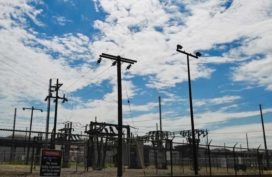
Algal Engineering designed the new 44kV overhead line connecting a substation in a powerplant to the grid . The design of the primary feeder included the protection system, pole details and calculations as well as the primary revenue metering system.
A new fibre optic and multipair copper lines were underbuilt on the same poles to provide communication and security equipment connections for the new substation.
The design package also included a double-circuit 13.8kV pole line between the substation and a downstream switchgear.
The scope of services included the following:
• Prepared single- and three-line diagrams for the new installation.
• Prepared layout drawings identifying all poles that had to be installed, all necessary pole framing, protections, anchoring, wiring and equipment sizes and installation notes.
• Prepared the Bill of Materials based on USF Standards.
• Prepared the pole frames details and wiring, anchoring and pole schedules.
• Prepared the sag and tension calculations and charts.
Algal Engineering was in charge of the design, installation and commissioning engineering support as well as the engineering oversight and project administration.

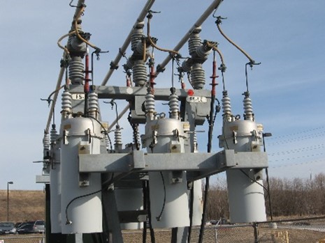
The purpose of the project was to upgrade the medium voltage (4.16kV) overhead feeder system to provide a closed loop configuration for certain feeders originating in the powerplant substation 44kV/4.16kV.
The intent was to improve the reliability of the system by implementing the looped feeder system as well as to provide more flexibility for maintenance switching and repairs services.
A summary of the scope of work is as follows:
- Installation of a new pad mounted disconnect switch for the feeders.
- Installation of a new overhead line on wood poles along the access road to be connected to a pad mounted switchgear, which connects other loads and also serves as the second open point.
- The new poles were to be equipped with new anchoring systems, framing, and comply with OESC and USF Standard design.
The engineering services included the following:
- Provided a load assessment and calculations to determine the extent of load migration between the feeders.
- Prepared the design briefing and presented it to the client for approval.
- Prepared site plan for overhead lines.
- Prepared the specification of all equipment (poles, line conductors, anchors, disconnect switches, interlock devices).
- Performed sag and tension calculations.
- Designed pole framing, anchoring, pole risers and the underground electrical systems.
- Modified the design of the interlocking system to prevent accidental paralleling of the two feeders.
- Provided Structural design for the disconnect switch concrete base and steel reinforcing.
- Designed new switchgears that are utilized as switching devices and open point withing the F2-F6 loop.
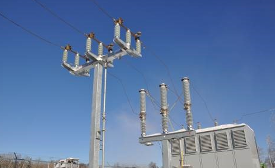
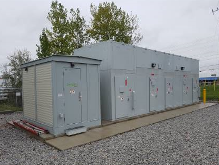
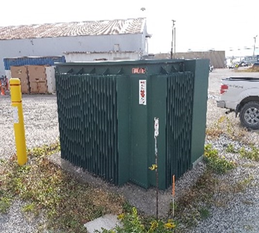
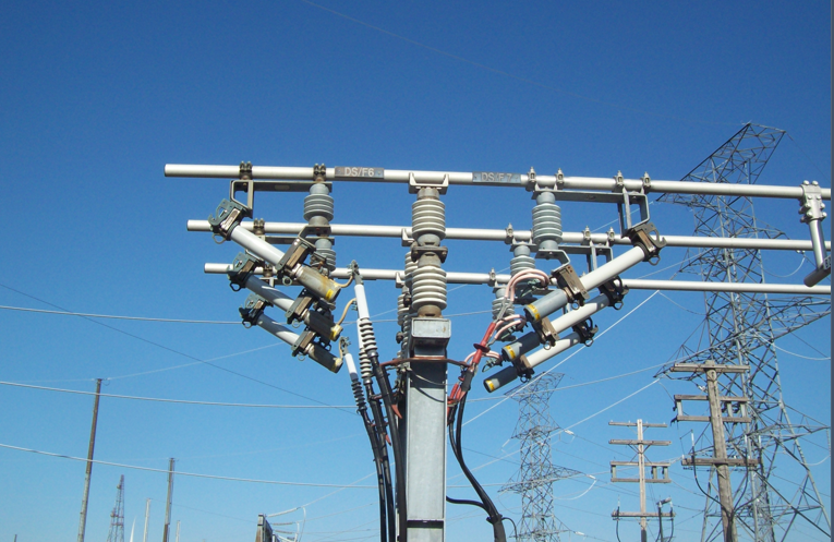
The scope for this project included the construction of an outdoor compound to house a new main output transformer (MOT), Revenue CTs and PTs on pedestals,
interrupter, switcher, lightning arresters and the O/H line exit structure for the connection to the Utility’s overhead line. The O/H line design entailed poles, complete with pole framing and anchoring.
The engineering services included the following:
- Performed a load assessment and calculations to determine the sizes of equipment and wiring.
- Prepared the site plan for the overhead lines.
- Prepared the equipment specification for poles, line conductors, anchors, disconnect switches and interlock devices.
- Performed sag and tension calculations.
- Designed the pole framing, anchoring, pole risers and the underground electrical systems.
- Prepared structural design for the concrete bases and metal structures for the exit to the overhead line.
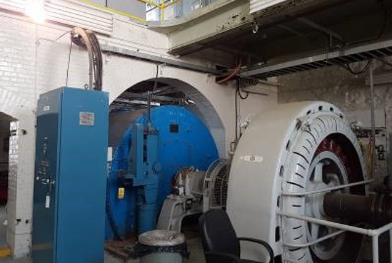
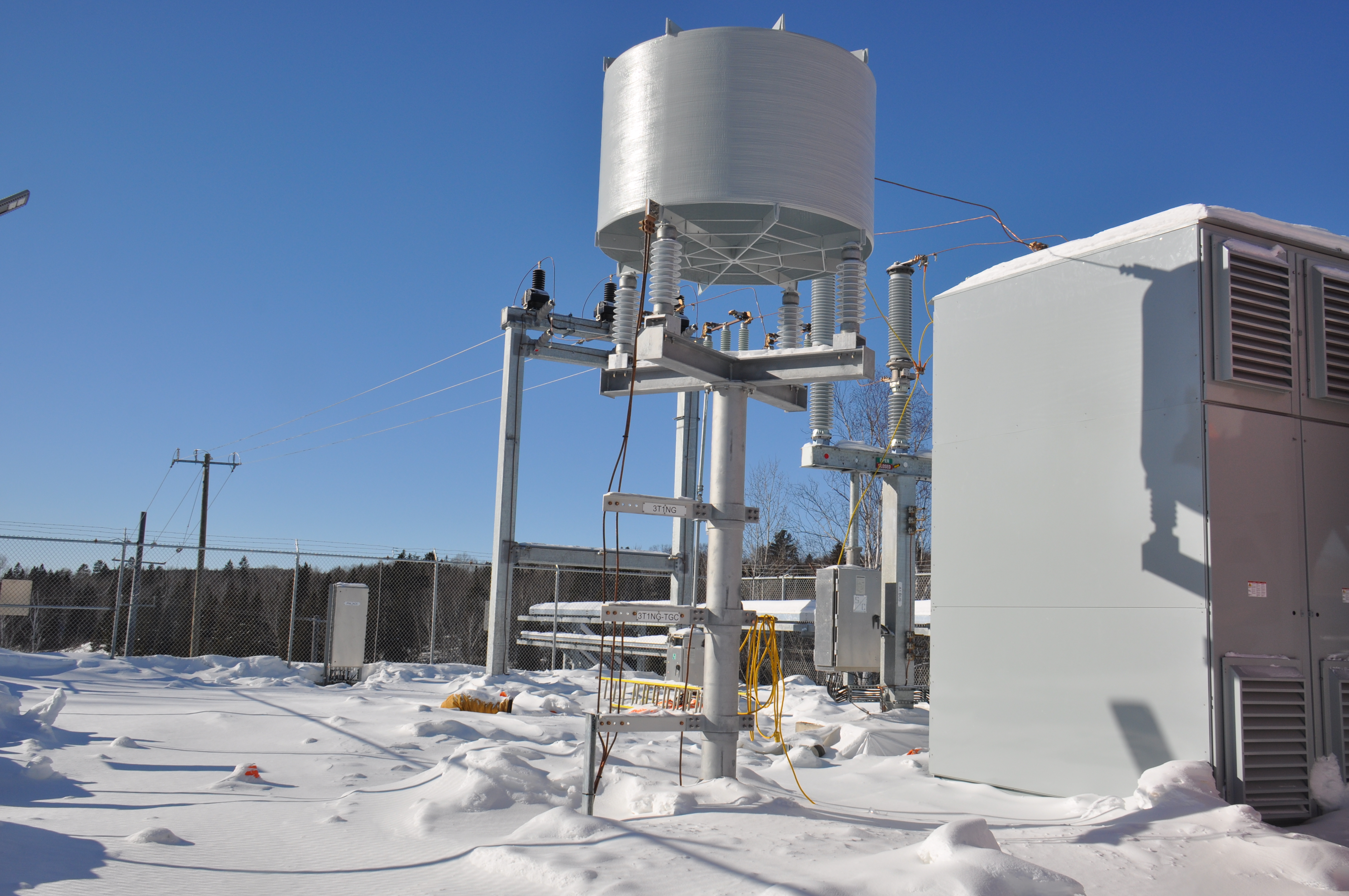
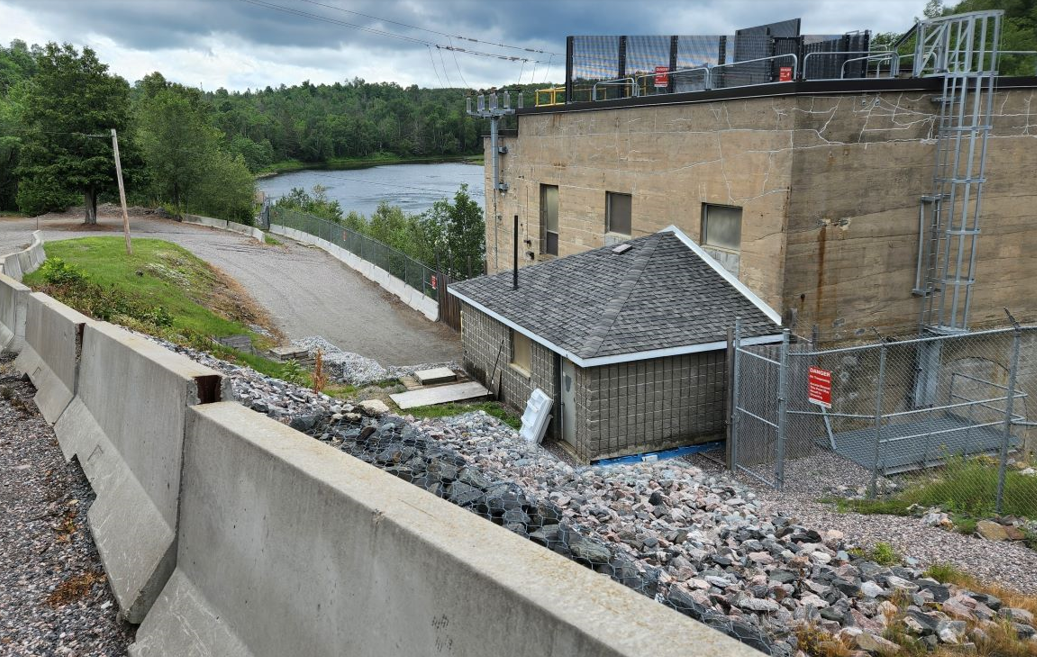
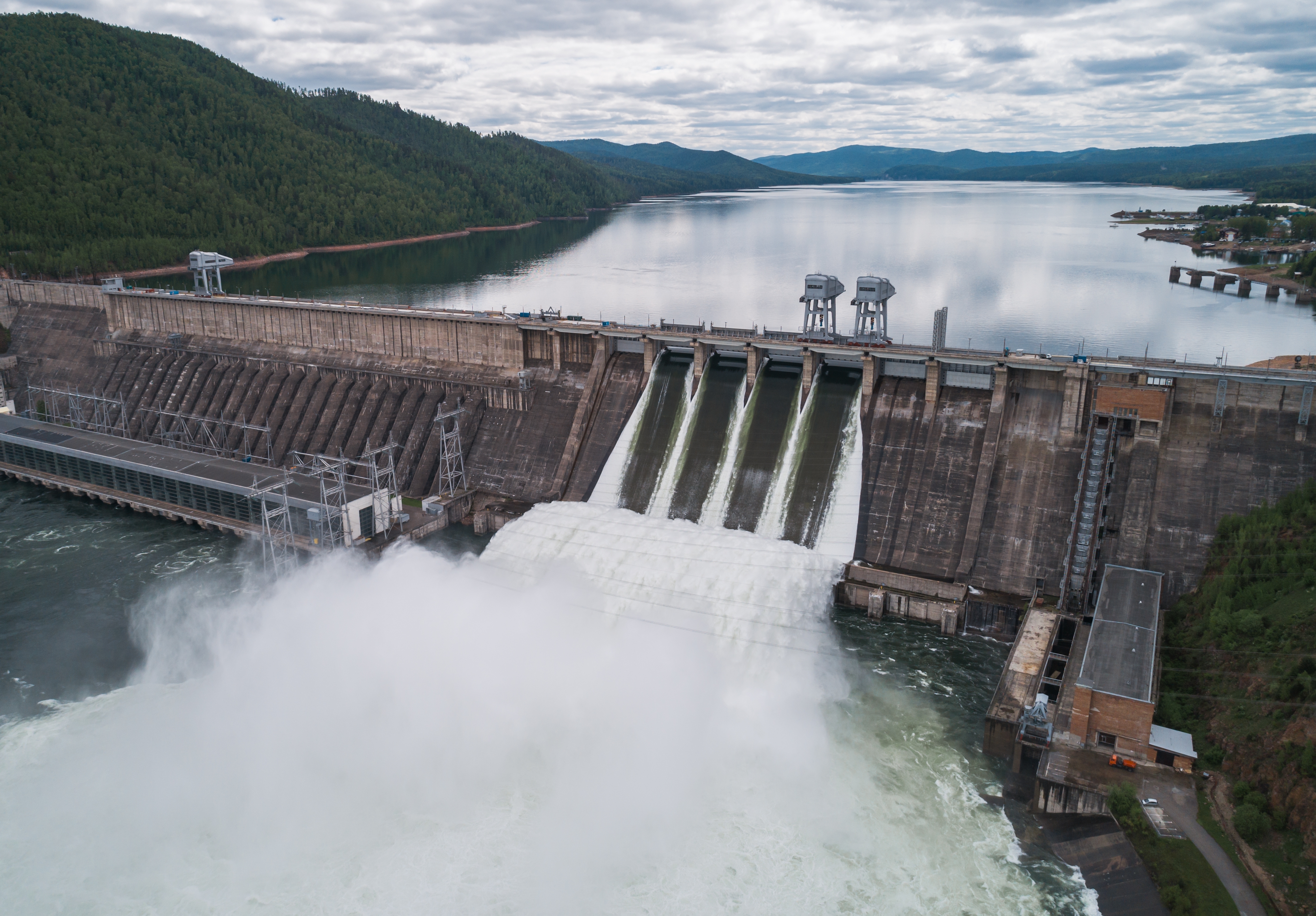
The station was a hydroelectric generating station owned and operated by Ontario Power Generation. It was connected to the Utility’s grid via an overhead line.
The Utility modernized the medium voltage grid in the surrounding area/region and changed the voltage form 22kV to 44kV for their grid.
The voltage change for the Utility line also imposed the requirement to change of the Power Plant’s main output transformer to match the new voltage level. Due to space limitations in the powerhouse, the new transformer and the other required switching and metering equipment had to be installed outdoors.
The scope included the construction of an outdoor compound to house a new main output transformer (MOT), Revenue CTs and PTs on pedestals,
an interrupter, a switcher, lightning arresters and the O/H line exit structure for connection to the Utility’s overhead line. The O/H line design also entailed poles, complete with pole framing and anchoring.
In addition, the scope included the upgrade of the SCADA system, the MOT protection upgrade and the transformer and line protection system.
In addition, the scope included the upgrade of the SCADA system, the MOT protection upgrade and the transformer and line protection system.
- Replacement of the protection relays
- Upgrade of the P&C cabinet which is integrated with the generator protection switchgear
- The re-design of the wiring and wiring management in the P&C cabinet
- Installation of new CTs and PTs for protection input and for metering.
- Revision of all of the Plant’s affected drawings for EWDs, CWDs and equipment layout.
- Preparation of the technical specification for the equipment as well as the Bill of Materials.
- Preparation of protection relay settings.
- Coordination and oversight of installation and commissioning activities related to the P&C scope.
The Mailing and Shipping Centre was one the top four most important facilities for the Canada Post’s operations. The facility had an emergency power generator for life and safety as well as some process equipment. However, the existing system did not have the capability for a quick connection for an alternate recovery generator in case of a critical or catastrophic failure of the Utility’s Power Supply.
Algal provided the design for the 600 V generator connection system to provide the full required capacity for a complete system recovery. The project scope included an automatic medium voltage transfer scheme to switch to the reserve 44kV Utility feeder in case the Primary Utility feeder fails.
Algal Engineering developed the design for the protection and control (P&C) systems to provide selective protections, automatic operation as well as remote monitoring and control via the Building Automation System (BAS). A P&C E-house was designed to house the protection rack and all other auxiliary equipment.
The P&C rack incorporated the protection relays for the generator breakers, the automatic transfer PLC controller, UPS, power distribution equipment, cabling and cable management, the HMI system and screen.
Our design included:
- P&C and auxiliary equipment specification.
- Protection and control diagrams, EWDs, CWDs.
- Bill of materials.
- ETAP studies, Protection settings.
- Protection philosophy.
- P&C rack layout, elevation and details.
- Power supply for the P&C system.
Algal Engineering provided detailed design for P&C system, installation and commissioning support.
The project at the OPG Hydroelectric Generating Station required Electrical Engineering for Protection and Controls upgrade including: transformer and line protections, power distribution, generator paralleling switchgear upgrade, communications system, lightning and surge protection, panels replacement, wiring, medium voltage overhead grid system and underground raceways, protective devices, switcher, interrupter, and insulators.
The scope included the construction of an outdoor substation compound which contained a new main output transformer (MOT), Revenue CTs and PTs on pedestals, an interrupter, a switcher, lightning arresters and cable connection to the Utility’s overhead line, complete with pole framing and anchoring.
The scope included the upgrade of the P&C and SCADA system as well as the construction of a communication tower and the associated communication e-house and full transformer and line protection upgrades.
The P&C scope included the following:
- Replacement of the protection relays.
- Upgrade of the P&C cabinet which is integrated with the generator protection switchgear.
- Re-design of the wiring and wiring management in the P&C cabinet.
- Implementation of new CTs and PTs for protection input and for metering.
- Revision of the OPG affected drawings for EWDs, CWDs and equipment layout.
- Preparation of the technical specification for the equipment and the Bill of Materials.
- Preparation of the protection relay settings.
- Coordination and oversight of installation and commissioning activities related to the P&C scope.
The intent of this project was the replacement of the protective relays of a Power Plant’s protection system - Main Generator and 500 kV LG Line, MOTs, SSTs and USTs.
Algal provided design replication for the complete replacement of protection relays, the reconfiguration of protection relay racks for two protection systems, and the field wiring assessment and upgrade for three units.
Algal’s scope was the replication of the design prepared by another company for another unit not in the scope of this project.
The upgraded protection system was designed to provide identical function-by-function coverage against electrical faults in the protected power equipment.
The P&C scope included the following:
- Replacement of the protection relays.
- Upgrade of the P&C cabinet.
- Re-design of the wiring and wiring management in the P&C cabinet.
- Installation of new CTs and PTs for protection input and for metering.
- Revision of the OPG affected drawings for EWDs, CWDs and equipment layout.
- Preparation of the technical specification for the equipment and the Bill of Materials.
- Preparation of the protection relay settings.
The purpose of this report was to assess the grounding to determine the tolerable and actual step and touch potentials in order to comply with IEEE std. 80-2000, IEEE Guide for Safety in AC Substation Grounding. This report also mae recommendations in order to bring the ground grid to IEEE 80 standards.
1. Performed revision of the Grounding Study considering the Utility’s new fault level and new primary fuses (100E) as determined by the 44kV/8kV coordination study. (As requested by the plant’s engineering team).
2. Grounding systems resistance measurements were also performed for the 8kV switchgear.
A complete assessment and testing of the existing grounding grid throughout Nuclear Power Plant site, inside and outside the Protected Area (PA).
Algal prepared an assessment of grounding and bonding connections to major power distribution equipment.
Algal also Prepared a comprehensive Grounding Study including analysis and recommendations.
Project Scope Description:
The purpose of this report was to perform a study on the nuclear power plant site and all buildings interconnected to its ground grid for the assessment of step and touch potentials and Ground Potential Rise (GPR). The study considered all interconnected buildings outside and inside the PA. The entire site’s grounding grid along with the interconnected buildings were modelled in ETAP 14.0. Also, Algal calculated an important substation’s split factor.
Calculations were performed as per IEEE Std. 80-2000 titled ‘IEEE Guide for Safety in AC Substation Grounding’, IEEE Std. 81 titled ‘IEEE Guide for measuring earth resistivity, ground impedance and earth surface potentials of a Grounding System’ and IEEE Standard 81.2 titled ‘IEEE Guide for measurement of impedance and safety characteristics of large, extended or interconnected grounding systems’.
- OPG ESSB Building - Arc Flash Studies using ETAP software
- OPG DNG Auxiliary Security Building -Short Circuit and Protection Coordination Studies
- Darlington Nuclear Arc Flash & Load Flow Study
- DNG Nuclear - Main Security Building Arc Flash and Load Flow Studies
- PNG DNG MSB Arc Flash Calculations Worst Case Scenarios - Substation DS1
- OPG DNG – Substations distribution – Protection Coordination, load flow, short circuit and arc flash Studies
- DNG Arc Flash Study - Entire NEF Site – 30 buildings
- DNG Load Flow Study – Entire NEF Site – 30 buildings
- Mold-Master Arena – Protection Coordination and Arc Flash Studies
- OPG DNG Computer and Maintenance bldg. - Load Flow, Short Circuit and Arc Flash Study
- DNG ESSB DLC Electrical Protection Arc Flash Studies
- DNG ESSB DLC Arc Flash Study
- OPG DNG ETAP Studies - Tetratech
- RWSB Power Distribution Studies (Arc Flash &Load Flow Short Circuit)
- OPG Learning Centre - Arc Flash, Load Flow & Short Circuit
- OPG RFRISA Building – Arc Flash, Short Circuit and Protection Coordination Studies
- OPG RWSB Building – Arc Flash, Short Circuit and Protection Coordination Studies
- Canada Post Gateway 44kV feeders– Arc Flash, Short Circuit and Protection Coordination Studies
- Queens Park Complex – Arc Flash, Short Circuit and Protection Coordination Studies
- OPG Sir Adam Beck GS – Arc Flash Study
- OPG - Pickering Facilities ETAP Studies
- OPG DNG – Update and consolidation of ETAP Studies
- OPG - DNGS - EME Storage Facility - ETAP Studies
- RWSB Update ETAP Studies for new 600V equipment
- OPG GS Arc Flash Study
- OPG Nuclear Plant- TMB Panel “A” Arc Flash Study
- OPG – DNG Water Treatment Plant Arc Flash Study for secondary side of Transformer Tie-In Temporary Construction Power
- Courthouse - Short circuit studies, protection coordination studies, arc flash study
- OPG High Voltage Transmission Lines - Short circuit study
- Discovery Harbor, High Voltage Electrical Studies
- Short circuit studies, arc flash studies
- Upper Canada Village Electrical Study, -Short circuit studies, protection coordination studies
- Whitney Block, Electrical Study - Arc flash study
This Feasibility Study was the first step of the planning stage for the plant’s power infrastructure upgrade to support the site development in preparation for DNGS Refurbishment projects. To support the extensive refurbishment project, new buildings, new parking lots and roads had to be built on the plant’s site. Accordingly, the main power distribution system throughout the site had to be upgraded.
The feasibility study provided OPG with a comprehensive analysis of the existing systems, future requirements, options, limitation constraints and, in order of magnitude, budget numbers for each option.
The Feasibility Study provided an engineering base for the detailed design scope definition.
The Scope of Feasibility Study was based on OPG’s Scope of Work Documents.
The Feasibility study presented a total of eight options and contemplated four options for each of two parts of the plant site. The options were presented along with advantages and disadvantages and associated implementation budget numbers.
The Ministry of the Environment’s (MOE) building had the physical attributes and proper site location for the implementation of renewable solar technologies. This report put forth three system options that could be feasibly installed at the site, whose installations would reduce the annual operating costs of the building and make an overall environmental impact.
The project addressed the construction feasibility and cost feasibility of photovoltaic electricity generation system and solar thermal hot water generation system at the site of the building.
The location for solar panels was explored, such as on roof or/and on the vertical facade as building integrated photovoltaics (BIPVs). It was understood that the installation would have significant public exposure and that aesthetics are important.
The following tasks were pursued:
- Reviewed the inventory of the building with electrical, mechanical and structural engineering staff.
- Examined current and future energy prices and their potential impact, as well as utility contracts.
- Described the PV and solar thermal projects for energy and cost evaluation.
- Modelled of the systems with the RETSCREEN software and provide reports in final report.
- Prepared cost-effectiveness ratings for each measure, presented as simple payback, in years to return the capital investment, or as long term (e.g. 20 year) lifecycle or present value costing.
- Recommended a new system to be installed along with an implementation plan defined using the above information.
- Recommended next steps such as required engineering specifications, and assistance of tendering process Provide a final report covering the above information.
Prepare load flow, short circuit, coordination and arc flash studies to evaluate the impact as a result of adding the switchgear SWGR-54 and Temporary Switchgear located at the site. The purpose of the studies is to confirm whether the configurations of the additional equipment are feasible and whether there is any adverse impact on the substations' 8.32kV and 13.8kV equipment and protections.
The scope of work covers the existing transformers and immediate upstream and downstream protection devices:
• Establish if the existing loads are supported by the new equipment configurations.
• Prepare ETAP Study to certify that such loads will not impede the existing station loads, and includes calculations for voltage drops, transformer loading and cable loading.
• Assessment of existing condition.
• Include major motors to take into account their fault contribution, as applicable.
• Provide fault levels for all buses within the scope of work.
• Verify that the momentary and interrupting capability rating of new equipment can adequately withstand a short circuit fault.
• Identify system deficiencies and propose upgrade actions to address such deficiencies, if required.
• Prepare protective device coordination at the connection interface point and identifying As Designed and Proposed configuration and protection settings, as applicable.
• Prepare the protective device settings list.
• Provide arc-flash incident energy, personal protective equipment (PPE) risk/hazard category number, and arc-flash labels for the proposed switchgears.
Scope of Work:
A. Support client with Regulatory Applications and Feasibility Studies within Grid Connection Scope
1. Support client in preparing the necessary documents and drawings that are needed as inputs to the:
a. IESO TFS
b. IESO SIA
c. HONI TFS
d. HONI CIA
e. CNSC LTC Application
f. Environmental Assessments
2. This support (1.) includes preparing system descriptions, reports and diagrams to outline switchyard conceptual requirements, designs and operation.
g. This will include, but is not limited to:
i. Protection System (Coordination between Switchyard and Facility)
ii. Control Schemes and Switchyard Control Authority Division
iii. Operational Philosophy
iv. Switchyard Equipment Specification (at a Conceptual/Preliminary level as per Study Applications)
B. Advance Conceptual Design of Switchyard and Interconnections with Facility and site
1. Update Switchyard Site Layout and Design to correspond updated site layout and construction lay down areas.
2. Advancing Station Service design and providing Switchyard Station Load Estimates – both AC and DC loads
3. Outlining and Providing estimates of Switchyard non-electrical service needs
4. Advancing the conceptual design of Switchyard HV/MV/LV connections with multiple Facilities
5. Providing technical input and direction to client's Geotechnical Study regarding Switchyard requirements
6. Providing technical input and direction to client's Grounding Study regarding Switchyard requirements
7. Supporting client in the process of obtaining required permits
C. Support client team on project planning activities such as identification of critical preliminary engineering deliverables and timeline.

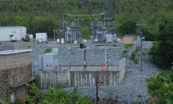
Algal Engineering was engaged to design a new substation to connect the hydroelectric generation station to the Hydro One grid via a 44 kV distribution system. Algal performed a study for the entire Generating Station along with the new substation and interconnected fences via the dam and on the north side of the river as well as the river ground loops. The studies accounted for various scenarios as an integrated grounding system and tolerable and actual step and touch potentials were determined in order to comply with IEEE Std. 80-2000, IEEE Guide for Safety in AC Substation Grounding and to assess Ground Potential Rise to ensure safety for this location.
The engineering analysis followed the following standards:
• IEEE Std. 81 - IEEE Guide for Measuring Earth Resistivity, Ground Impedance and Earth Surface Potentials of a Ground System.
• IEEE Std. 81.2 Standard titled, IEEE Guide for measurement of Impedance and Safety Characteristics of Large, Extended or Interconnected grounding systems.
The deliverable of this project included:
• Grounding Study with analysis of various scenarios
• Computer models for the grounding grid for each scenario
• GPR and Step and Touch Potential calculations and charts
• Grounding grid design – layout, details and material specification
• Bill of materials.
• Details for the remote grounding grid and the water grounding loop.
• Verification of the grid performance through site measurements.
Algal was engaged to design a ground grid for the new 44 kV substation at the client generation station. The Generating Station (GS) Powerhouse was already interconnected with the Hydro One substation ground grid. The new 44 kV substation ground grid will be located between the Hydro One substation and the GS powerhouse.
The GS powerhouse, the new 44 kV substation ground grid, the penstocks, dam and the shop were studied as standalone grid. An additional river ground loop was studied as well connected to an integrated grounding system. Tolerable and actual step and touch potentials were determined in order to comply with IEEE std. 80-2013, IEEE Guide for Safety in AC Substation Grounding; and to assess Ground Potential Rise to ensure safety for this location and also as per IEEE std 81, titled IEEE Guide for measuring earth resistivity, Ground Impedance and Earth surface Potentials of a Ground System and IEEE standard 81.2 titled, IEEE Guide for measurement of Impedance and safety characteristics of large, extended or interconnected grounding systems.

The purpose of this study was to evaluate the grounding of the Auxiliary Security Building at the client's nuclear facility; determine the tolerable and actual step and touch potentials in order to comply with IEEE std. 80-2000, IEEE Guide for Safety in AC Substation Grounding; and to assess Ground Potential Rise to ensure safety for this location.
Algal was engaged to design a ground grid for a microwave tower and an adjacent telecommunications shack, model and evaluate the entire GS ground grid and also if applicable, auxiliary ground river loops for generation station site, using ETAP software, ensure that step and touch potentials and GPR meet IEEE standard 80. Design lightning protection for the microwave tower. Perform a study integrating the microwave tower and telecommunications shack into the entire GS ground grid, model the entire GS grid and river loops.

Design a ground grid for a microwave tower and an adjacent telecommunications shack, model and evaluate the entire GS ground grid and if applicable auxiliary ground river loops, using ETAP software, ensure that step and touch potentials and GPR meet IEEE standard 80. Design lightning protection for the microwave tower. Perform a study integrating the microwave tower and telecommunications shack into the entire GS ground grid, model the entire GS grid and river loops
Algal provided an Assessment Study, installed power quality monitoring analyzers on
the main feeders and collected all necessary data for a period of 7 days. The
measurements provided information for Voltage fluctuation, the power factor rate and
total harmonic distortion; the maximum current total harmonic distortion.
Based on obtained information we determined the size of the power factor correction
units. The Design brought the system into compliance with IEEE 519-1992.
• Algal determined the size of the Power Factor Correction Unit c/w harmonic
reactor incorporated in the Capacitor unit.
• Algal provided the calculations to increase the transmission capacity of active
power, maintaining voltage system, minimizing energy losses, and correcting load
power factor.
Algal designed and Installed the replacement of the 250KVAR 460 V
capacitor bank with an EATON power factor capacitor
- Algal also provided for a REX reactor
The equipment has been connected to the existing switchboard with existing wiring.
1. Algal performed an investigation of all electrical distribution connected to normal power and base building emergency power.
2. A Load test was performed on all distribution equipment to ensure there were no capacity issues.
3. Algal identified all breaker panels throughout the facility and updated single line diagram of the system.
4. Conducted infra-red scanning on all distribution equipment that is in scope.
5. Performed Electrical Studies.
6. Performed power monitoring on three points in the system.
7. Provided recommendations and upgrades to the system.
Algal prepared an assessment of the existing 600V main distribution system located in the Main Electrical Room Bldg. The assessment was based on power monitoring on the main 600V bus. The 600V distribution equipment in the Compass Building was fed from the 600V Section of the main switchgear in a Building wing (located at basement level Building)
Algal determined the size of the Power Factor Correction Unit c/w harmonic reactor incorporated in the Capacitor unit.

Algal provided a Feasibility Study, based on the findings and observations, considering economical and technical aspect, we identified three options for the intended MCC upgrades. The approved option for Detailed Design phase was to Complete replacement of the three MCC assemblies with three new matching MCC assemblies.
For this project, Algal was retained to produce a study and provide engineering
design and support services for MCC replacements in a courthouse. The scope
included:
1) Produce an Assessment Report and conduct a Feasibility Analysis for the
retrofit of the existing MCC at same location and analyze/compare it to the
option of completing a replacement of the MCC and relocation to an alternate
location. Additionally, Algal analyzed the option and implications of the conversion of
all MCCs from 416V to 600V.
2) Algal also provided services for the development of a Detailed Design and
Project Administration for the approved MCC upgrade option. This included:
• Room Layouts, Front Elevations Drawings
• Single line diagrams
• Connections wiring diagrams
• Specification
• Equipment Data Sheets
• Bill of Materials
The scope of this project was to:
• Replace six old motors with high efficiency alternatives, suitable for operation
with VFDs. (600V)
• Install new wiring in new overhead conduits for the new six motors and VFDs.
• Install six new VFDs. (600V)
• Install two new MCCs sections rated for 600V, 600A c/w six breaker
compartments and a main breaker.
• Demolition work related to six motors and related starters.
• A new concrete housekeeping pad was required for the two MCC sections.

The project consisted of:
- Complete replacement of all five MCCs.
- Tracing wiring and documentation of 21 MCC wrappers on five MCC lineups at the
correctional services building sight.
- Preparation of control wiring diagrams.
Algal provided Design and Installation Support for the DC monitoring system for a
switchgear located on the powerplant site. This included the following elements:
- DC protection upgrade, remote breakers control (open/closed).
- Modifications required for switchgear enclosure and concrete pad for proper and easier racking out of breakers.
- Modifications required for switchgear enclosure and breaker enclosure and breaker racking system.
